How stable are construction profiles?
Posted on Apr 16, 2025
Step by step explanation of how to calculate whether a structural profile can bear a load or be permanently deformed under it.
Construction profiles are highly durable and, to a certain extent, flexible. We will explain step by step, using a practical example, how to determine whether the load is too great, and the material will be permanently deformed and damaged.
When does a load lead to permanent deformation?
It is perfectly logical for a construction profile to bend under load. How much this deflection occurs depends largely on the profile and its length, its own weight, the additional weight, the load distribution and the type of mounting. At first glance, the formulas for calculating deflection appear very complex. That is why we have dedicated a separate blog post to this topic, in which we explain each individual parameter and the calculation in small, understandable steps. But when is this load too high? When does the weight affect permanent deformation? We will deal with this question in detail in this article.
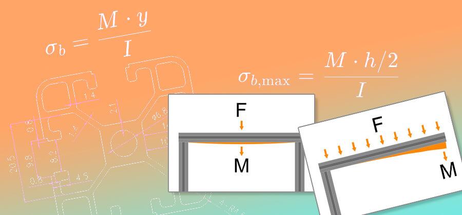
First, a little theory about bending stress
To calculate the bending stress, i.e. the stress acting mechanically on the material due to loading, we need to know how strong the material is. It helps to take a look at the material's data sheet, because we need to determine the value of the yield strength Re (which is also referred to as yield stress or yield point. This can vary greatly from material to material. Even with a construction profile made of aluminium, a closer look is important, because not all aluminium is the same. The specific alloy is important here in order to determine the yield point.
The yield point of a material describes the stress at which it is plastically deformed, for example the material begins to deform permanently without returning to its original shape when the load is removed. It is therefore an important mechanical property that indicates how much stress a material can withstand before it begins to deform permanently and, like the modulus of elasticity, is expressed in pascals or N/mm², as another important physical quantity. For aluminium, the yield point marks the point at which elastic deformation (which is reversible) changes into plastic deformation (which is irreversible). This means that if the yield point is exceeded, the aluminium profile will undergo permanent deformation due to stretching. Our construction profiles are made of a high-quality EN AW 6063 T5 aluminium alloy with an incredible yield strength of 292 MPa. MPa can be exchanged for the unit N/mm², which is also the unit of flexural stress under load and thus makes it easier to compare.
Another important value is the section modulus, which is the same for both the X and Y axes in our construction profiles, since the profile design is symmetrical. The section modulus is always specific to the profile cross-section.
The section modulus W of our construction profiles
- Construction profile 20x20, groove 6:Section modulus Wx, Wy: 0,71cm3
- Construction profile 30x30, groove 8:Section modulus Wx, Wy: 1,57cm3
- Construction profile 40x40, groove 8:Section modulus Wx, Wy: 3,58cm3
In addition to the physical data, we now also need to know the weight acting on the profile. We also need to know the length of the profile, because a longer profile will show a higher value for the bending stress under this weight than the same profile in a shorter version. Last but not least, the type of mounting and the load distribution also play a role. We have already made it clear in the explanations on calculating the deflection that these parameters sometimes have a significant effect on the load-bearing capacity of a construction profile.
Calculating the bending stress – here's how it's done!
Parameters for calculating the bending stress σb
- M The bending moment in N*mm of the load case
- W The section modulus of the profile cross-section in mm3
General formula for bending stress
The bending moment M depends on the load F and the length L of the profile. Whether the load is evenly distributed or applied at a single point is just as important for the calculation as the type of mounting, because so-called load cases with different formulas and constant factors for calculating the bending moment can be derived from these. However, the bending moment of a particular load case is an essential part of the formula for calculating the bending stress.
The load F is a force that is measured in newtons (N). This is calculated by simply multiplying the mass m, for example the weight (kg), that acts on the profile by the gravitational constant g. On earth, this has a value of approx. 9.81kg*m/s 2 and is also referred to in common language as the force of gravity. The Formula for converting the weight load F is explained in detail in the blog article on calculating deflection. There, the formula for calculating the surface load q with even load distribution is described in detail.
The bending moment M for load cases where the profile is mounted on both sides
Formula for the bending moment with even load distribution q
The formula for the bending moment due to weight loading F with a centred load
The bending moment M for load cases where the profile is mounted on one side
Formula for the bending moment with even load distribution q
The formula for the bending moment due to weight loading F at the end of the open profile
A practical example of calculating bending stress
Let's assume that we want to convert a van and build a bed frame out of construction profiles on the loading area. For this, we use construction profiles in 40x40mm with an 8mm groove in a length of 2 metres for the long side, which are firmly attached to the support posts on both sides. The expected weight that will act on the profile consists of the sum of the individual weights of the mattress, slatted frame, bed linen and your own body weight, so we assume a total mass of 100kg here. We normally lie in bed, so we can assume a distributed weight load, but sometimes we also sit in the middle of the bed. This also gives us a mixed load effect. Therefore, we will play it safe and calculate the bending stress for a centred point load below.
Given parameters for calculating the bending stress σb
- Profile length L: 2.000mm
- Mass loading m: 100kg
- Section modulus W: 3,58cm3
- Yield point of the profile Re: 292MPa (or N/mm2)
- Lastfall: Beam with uniformly distributed load and supports on both sides q
First of all, we convert the mass of 100 kilograms into force in newtons.
Now that we know the force of 981 newtons, we will use it to calculate the distributed load needed to calculate the bending stress when the load is applied evenly. We can use the force we just calculated directly for the bending stress when the load is applied in the centre.
Our calculation shows that a force of 0.4905 newtons acts on each millimetre of a profile with a force due to weight loading of 981 newtons. We now use this value to calculate the bending moment.
Now for the last step. We calculate the bending stress. However, we must also make sure here that the yield point is usually given in cm 3 which we have to convert to the same units in mm 3. But that's very easy, because one cubic centimetre is 1cm*1cm*1cm or, expressed in millimetres, 10mm*10mm*10mm, which corresponds to 1000mm3.
Since the value of the bending stress of rounded 68.5N/mm 2 is well below the yield strength of the aluminium used, which has a value of 292N/mm2 , there is no risk of permanent deformation under a uniformly distributed load of 100kg.
Given parameters for calculating the bending stress σb
- Profile length L: 2.000mm
- Weight load F: 981N
- Section modulus of profile W: 3,58cm3
- Yield point of the profile Re: 292MPa (or N/mm2)
- Load case: Beam supported on both sides with a load acting in the centre F
Below, we calculate the bending stress when the weight acts as a point load on the same construction. This is the maximum type of load that can act on a profile mounted on both sides. This is not entirely true for our example, since at least the slatted frame and the mattress are to be understood as distributed load. If we leave that out for the moment, it provides a very good indication of whether the construction will suffer permanent damage due to deformation under the load, or whether it can bear it without hesitation.
Even with the load applied in the centre and at its full weight of 100 kg, the bending stress is rounded off at 137 N/mm. 2, which is below the yield strength of the aluminium profile. Only at a weight of more than 213 kg can an irreversible deformation of the profile be expected based on the material properties of the aluminium alloy used and the profile cross-section.
We hope that the explanations of the calculation of the bending stress in our construction profiles are helpful and easy to understand. The formulas in the article refer to our profiles, but they can also be used for other materials such as wooden beams or plastic plates, if you know the corresponding values for the yield point and the section modulus of the desired material and insert them into the formula. The information is usually listed in the technical data in the area of the mechanical material properties in the manufacturer's data sheets.
If you want to stay up to date, want to know what moves us and what is going on in our online shop, follow us on Instagram und Facebook. We appreciate every like.
Your Sascha from S-Polytec