
Drilling HPL sheets – drill bits, fixed points and sliding points
Posted on Aug 6, 2026
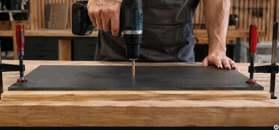
Drilling HPL sheets requires a sharp tool, secure support and careful hole-pattern planning. In this blog, we explain how to produce clean holes with a solid-carbide HPL drill bit and prepare fixed points and sliding points to suit the fixing method.
For clean holes, HPL sheets must be supported fully and securely, clamped reliably and machined with a sharp drill bit suitable for the hard laminate. Particularly precise results can be achieved with a solid-carbide HPL drill bit featuring a fine centring point.
In this blog, we show you how to plan, mark and drill holes correctly. You will also learn how fixed points differ from sliding points, which hole diameters are suitable for screw and rivet connections, and how to prepare HPL sheets for stress-free installation.
Drilling HPL sheets: what is important?
HPL sheets have a hard, durable surface that requires a sharp, wear-resistant tool for drilling. Unsuitable or blunt drill bits can wander across the surface, lose their sharpness quickly or produce rough hole edges.
A suitable HPL drill bit, a fully supported sheet and controlled guidance of the machine are therefore essential for precise holes. The speed, feed and contact pressure must also be selected so that the drill bit cuts cleanly without generating excessive heat.
For mechanically fixed facade, balcony or cladding sheets, a distinction must also be made between fixed points and sliding points. The fixed point defines the position of the sheet. Sliding points have larger holes so that the HPL sheet can accommodate material-related dimensional changes under changing environmental conditions.
Important: Not every hole in an HPL sheet is automatically a fixed or sliding point. This distinction is particularly relevant for mechanically fixed sheets that may move as temperatures and environmental conditions change.
Plan the cutting, cut-outs and holes together before beginning the machining process. Guidance on tool selection and controlling the cut can be found in our blog on cutting HPL sheets.
Which drill bit is suitable for HPL sheets?
For drilling HPL sheets, we recommend a solid-carbide drill bit designed specifically for hard facade and compact sheets. Solid carbide is particularly wear-resistant on the hard HPL surface and is therefore also suitable for repeated drilling.
The S-Polytec solid-carbide HPL drill bit features a special drill-head geometry with sharp cutting edges. Its fine centring point makes precise positioning on the marking easier and reduces the risk of the drill bit slipping across the hard decorative surface.
The wide flutes and adapted spiral geometry assist chip removal. This helps to reduce excessive heat generation, provided an appropriate speed and steady feed are used without high contact pressure.
| Feature | S-Polytec HPL drill-bit specification |
|---|---|
| Material | Solid carbide with hardened cutting edge |
| Drill type | Right-hand twist drill |
| Drill head | Special geometry for hard sheet surfaces |
| Centring | Fine, sharp centring point |
| Flute length | 25 mm |
| Overall length | 80 mm |
| Shank | Cylindrical shank |
| Suitable machines | Drill, cordless drill/driver or suitable pillar drill without impact action |
Conventional wood, metal or universal drill bits should not automatically be regarded as equivalent alternatives. Whether individual holes can be produced with them depends on the tool's quality, geometry and sharpness and on the application. For precise, repeatable fixing holes, a purpose-designed solid-carbide HPL drill bit is the preferred solution.
When using the S-Polytec solid-carbide HPL drill bit, additional pilot drilling with a smaller drill bit is generally not necessary. Its sharp centring point allows the drill bit to be positioned directly on the marked centre of the hole.
Caution: The impact action of an impact drill/driver must be disabled completely. Impact can damage the cutting edge of the HPL drill bit and impair the quality of the hole.
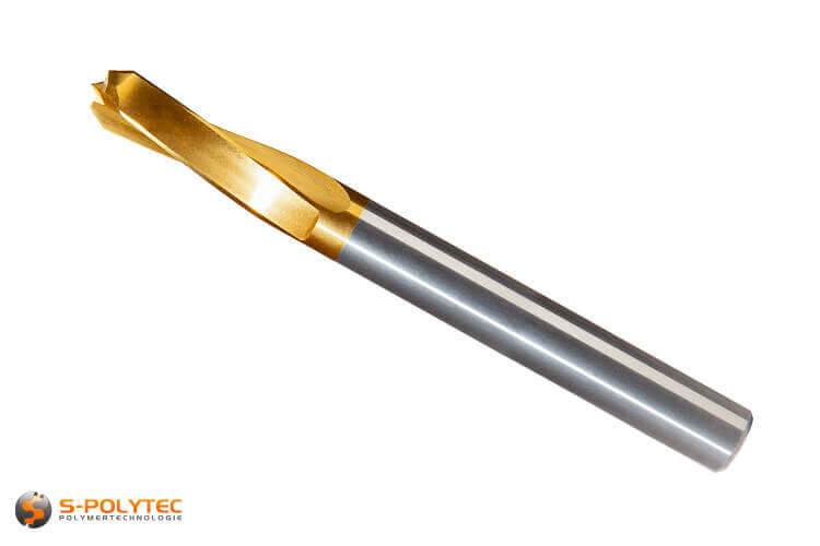
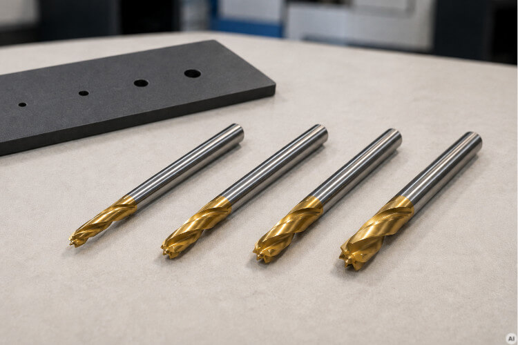
The sharp centring point makes accurate positioning easier. Click the product image to go directly to the S-Polytec solid-carbide HPL drill bit.
Plan the hole pattern and fixing method in advance
The complete hole pattern should be established before the first marking is transferred to the sheet. The positions and diameters of the holes depend not only on the desired appearance, but also on the sheet format, substructure, fixing and subsequent load.
- Define the sheet format: Determine the length, width, thickness and orientation of the HPL sheet.
- Check the substructure: Inspect the position, width and arrangement of the supporting profiles or battens.
- Select the fixing: Decide in advance whether facade screws, balcony screws or facade rivets will be used.
- Define the fixed point: Establish one fixing point that determines the position.
- Plan the sliding points: Provide the remaining fixing holes with the necessary movement clearance.
- Check the edge areas: Position holes with sufficient clearance from sheet edges, cut-outs and corners.
- Allow for joints: When using several sheets, plan the necessary movement clearance between components.
The hole pattern must align with the substructure. A perfectly drilled hole in the HPL sheet is unusable if there is no load-bearing profile behind it or the fixing cannot be positioned centrally in the substructure.
Consider material movement when planning the hole pattern
The dimensions of HPL sheets can change as temperatures and environmental conditions vary. If several rigid fixing points prevent this movement, stresses, deformation or damage to the sheet and fixings may occur.
The expected material movement therefore affects the required size of the sliding-point holes and the necessary clearance between individual components. Careful planning is particularly important for dark HPL sheets because dark surfaces can become hotter in direct sunlight.
The possible temperature-related change in length can be estimated using a thermal expansion calculator.
For facades, balcony cladding and other outdoor applications, the sheet, substructure and fixings must be considered as one coordinated system. The specific dimensions depend on the selected sheet, the installation situation and the requirements of the relevant fixing system.
If you are planning a free-standing privacy screen made from HPL sheets in the garden or on the patio, the panel layout, sheet thickness, posts, substructure, wind load, movement clearance and anchoring must also be considered together. Our blog Build your own privacy screen from HPL sheets shows how to coordinate these factors and construct the screen step by step.
Which tools and equipment are required?
In addition to a suitable HPL drill bit, clean holes require a stable work surface, a continuous sacrificial backing board and clamps that reliably prevent the workpiece from moving.
- For measuring: Tape measure and square.
- For marking: A clearly visible pen suitable for the surface and masking tape if required.
- For drilling: Cordless drill/driver or drill with variable speed and disabled impact action.
- For perpendicular series drilling: A pillar drill, provided the sheet can be supported fully and securely.
- As the drilling tool: Solid-carbide HPL drill bit with centring point in the required diameter.
- As a backing: A flat sacrificial board made of wood or a suitable plastic.
- For clamping: Correctly positioned screw clamps or quick-action clamps with suitable protective pads.
- For occupational safety: Safety glasses and effective extraction or good dust removal.
For several identical components, a drilling template can help transfer the drilling points to each HPL sheet in the same position. The template must be positioned securely and must not move while marking or drilling.
A pillar drill is particularly suitable for smaller workpieces that lie fully on the machine table and can be clamped safely. Large HPL sheets must not be machined using improvised or partial support.
Safety: Check the drill bit for damage before use. Its centring point and cutting edges are very sharp. Keep the HPL drill bit in its protective sleeve before and after use.
Preparing and securing the HPL sheet correctly
Place the HPL sheet fully and evenly on a flat sacrificial backing board. The backing must support the drill's exit side directly. The drilling point must not project beyond the support or lie above a void.
Secure the HPL sheet so that it cannot slide, turn or lift. Every clamp must actually clamp the sheet to the backing or work surface beneath it. Clamps that merely touch the edge or have no firm counter-support do not provide reliable security.
- 1. Check the surface: Inspect the HPL sheet for damage and dirt.
- 2. Leave the protective film in place: If a suitable protective film is present, leave it on the sheet during machining.
- 3. Mark the drilling points: Transfer all hole centres in accordance with the planned hole pattern.
- 4. Check the dimensions: Recheck edge distances, centre distances and alignment with the substructure.
- 5. Position the backing board: Support the HPL sheet across its entire surface without any voids.
- 6. Clamp the workpiece: Secure the sheet and backing effectively with minimal vibration.
- 7. Check the drilling path: Ensure that the drill bit, machine and chuck cannot collide with clamps or the work surface.
The HPL drill bit's centring point allows precise positioning on the marking. A forceful centre-punch strike is not necessary and should be avoided on the hard decorative surface.
A strip of masking tape can make the drilling points easier to mark visibly and provide additional protection around the marked area. However, the tape does not replace the HPL drill bit's centring point or secure clamping of the sheet.
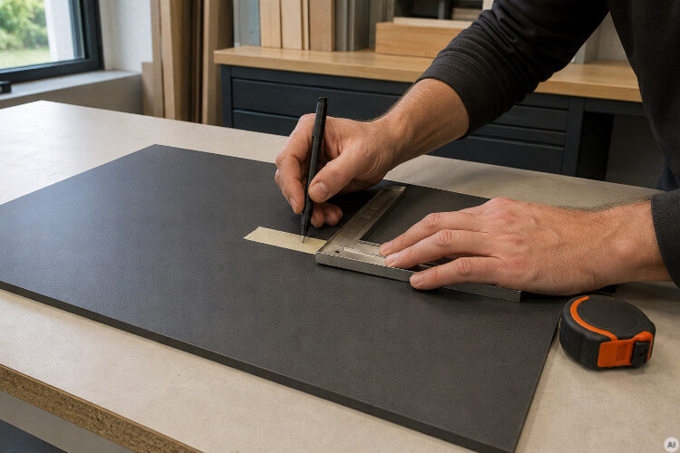
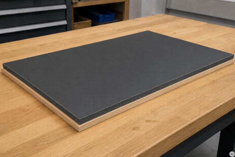
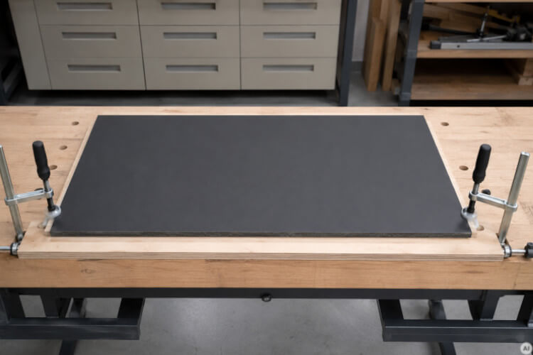
Transfer the drilling points accurately, support the HPL sheet across its full surface and clamp all components together securely.
Practical tip: If possible, first drill a test hole in an offcut of the same sheet type and thickness. This allows you to check the speed, feed and drilling result before machining the finished sheet.
Drilling HPL sheets step by step
1. Insert the HPL drill bit securely
Clamp the cylindrical shank of the solid-carbide drill bit straight and sufficiently deep in the chuck. Then check that the bit is held securely and does not wobble visibly when rotated slowly.
2. Set the machine correctly
Set the drill or cordless drill/driver to drilling without impact. Begin with a moderate speed suitable for the drill diameter. Larger diameters are generally drilled more slowly than smaller diameters.
Increase the speed only if the drill bit cuts cleanly, chips are removed reliably and no excessive heat develops. One universal speed cannot be specified for every machine, drill diameter and sheet thickness.
The tool and machine manufacturer's instructions and a controlled drilling process without high heat, excessive contact pressure or visible damage to the hole edges are decisive.
3. Position the centring point on the marking
Place the centring point exactly on the marked hole centre. Hold the machine perpendicular to the sheet surface. Holding the machine at an angle can produce a skewed hole, one-sided exit or reduced movement clearance.
4. Drill with a steady feed
Start the machine in a controlled manner and guide the drill bit through the sheet with a steady feed. Do not apply high pressure. The sharp cutting edges should cut the material rather than being forced into the sheet.
Excessive pressure can stress the drill bit and surface. Conversely, feeding too slowly so that the drill bit rubs in the hole for a prolonged period can create unnecessary heat. Therefore, maintain steady progress and unobstructed chip removal.
5. Drill through the exit side in a controlled manner
The sacrificial board beneath supports the exit side. Guide the drill bit straight through the HPL sheet and only as far into the backing as necessary to complete the through-hole.
6. Withdraw the drill bit straight
After penetrating the sheet, withdraw the drill bit without tilting it sideways. Levering sideways with the drill bit running can alter the hole diameter uncontrollably and damage the hole edges.
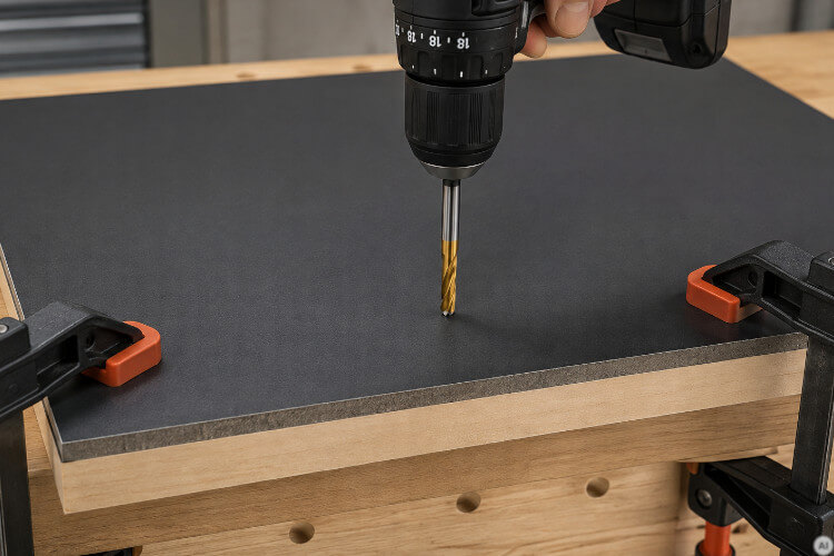
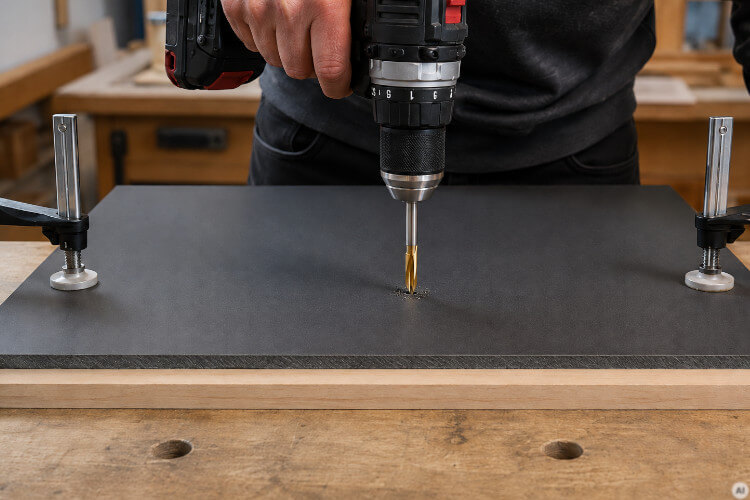
Position the HPL drill bit perpendicularly and guide it through the fully supported sheet in a controlled manner without high pressure.
Stop the process: Stop if the sheet moves, the machine tilts, the drill bit wanders visibly or unusually high heat develops. Then check the support, clamping, speed and condition of the tool.
Fixed points, sliding points and suitable hole diameters
For mechanically fixed HPL sheets outdoors, the fixings must position the sheet securely without completely preventing material movement. Many stress-free installation systems therefore combine one defined fixed point per sheet with several sliding points.
What is the purpose of the fixed point?
The fixed point defines the position of the HPL sheet on the substructure. It prevents the entire component from shifting uncontrollably as temperatures change. Depending on the fixing system, a hole matching the fixing is used for this purpose.
For a riveted connection on an aluminium substructure, a hole diameter of 5.1 mm is generally used for the fixed point. For screw connections using suitable facade or balcony screws, the fixed point can be drilled to 6.0 mm. The specific design must always match the fixing system used.
What is the purpose of a sliding point?
Sliding points hold the HPL sheet against the substructure while allowing limited movement around the shank of the fixing. The hole in the sheet is therefore made larger than the shank of the screw or rivet.
Hole diameters of approximately 8 to 10 mm are often used for sliding points in HPL sheets. The diameter actually required depends, among other factors, on the fixing, sheet format, fixing method and intended movement clearance.
| Fixing method | Fixed point in the HPL sheet | Sliding point in the HPL sheet |
|---|---|---|
| Facade rivets on an aluminium substructure | Usually 5.1 mm | Approximately 8 to 10 mm depending on the system |
| Facade screws on a timber substructure | Often 6.0 mm | Often 8.0 mm |
| Balcony screws on a metal substructure | Often 6.0 mm | Depends on the screw, sheet format and installation system |
The table provides guidance for the drill bits and fixings available from S-Polytec. The specific requirements of the sheet and fixing system used always take precedence.
Our blog on fastening HPL sheets explains how the prepared fixed and sliding points are subsequently fitted with facade screws, balcony screws or facade rivets.
Treat the HPL sheet and substructure separately
For a sliding point, only the hole in the HPL sheet is enlarged. The hole in an aluminium substructure remains matched to the shank of the intended facade rivet. An enlarged hole in the substructure would impair reliable guidance of the rivet.
For screw connections, the substructure must likewise be prepared to suit the screw used. The larger sliding-point hole in the HPL sheet must not be transferred to timber, aluminium or steel profiles without checking.
Centre the fixing in the sliding point
The screw or rivet should be centred in the enlarged hole. If the fixing already rests against one side of the hole, the necessary movement path is available in only one direction.
During subsequent installation, sliding points must not be clamped so tightly that the intended sheet movement is blocked. The connection must not secure the HPL sheet like an additional fixed point.
Suitable facade screws and facade rivets must be coordinated with the sheet, substructure and installation situation.
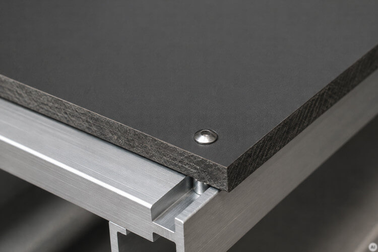
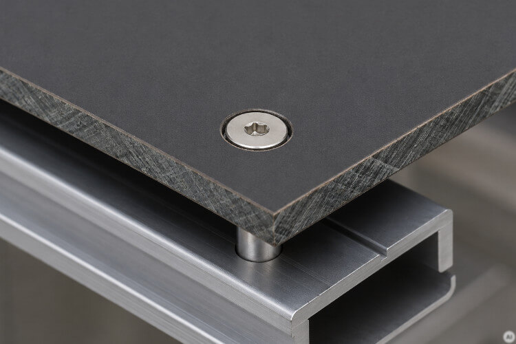
The fixed point determines the sheet's position. The larger sliding-point hole provides the necessary movement clearance.
Consider edge and fixing distances
Holes must not be positioned arbitrarily close to sheet edges, corners or cut-outs. Insufficient edge distance can weaken the remaining material cross-section and increase the risk of chipping or damage during installation.
One universally applicable measurement cannot be specified for every HPL sheet and application. The required edge distance depends on the following factors, among others:
- Sheet thickness: Thinner and thicker HPL sheets may have different structural requirements.
- Sheet format: Large sheets require a hole pattern coordinated with the format and substructure.
- Fixing: Screws and rivets differ in their shank, head and hole diameters.
- Substructure: The position, width and material of the profiles or battens influence the hole positions.
- Load: Wind, dead weight and mechanical stresses must be considered.
- Installation situation: Interior cladding, facades and balcony infills have different requirements.
The distances between individual fixing points also depend on the sheet format, sheet thickness, substructure, fixing system and loads. The technical requirements of the sheet and fixing system used are decisive.
Planning note: Different requirements apply to purely decorative cladding and an HPL sheet used as a fall-protection balcony infill. Safety-critical, load-bearing or building-regulated applications require professional planning and suitable system verification.
Inspecting and finishing the holes
Remove loose drilling chips after drilling and inspect every hole before installing the sheet. A visual inspection helps identify damaged hole edges, incorrect diameters or deviations in the hole pattern at an early stage.
- Position: Is the centre at the intended position and aligned with the substructure?
- Diameter: Does the hole correspond to the intended fixed or sliding point?
- Perpendicularity: Does the hole run straight through the sheet?
- Hole edge: Are the front and back free of significant chipping?
- Surface: Is the decorative finish around the hole undamaged?
- Movement clearance: Can the fixing be centred in the sliding point?
Small burrs can be removed carefully. Use only a suitable tool and work exclusively on the edge of the hole. Do not sand a large area of the decorative surface.
A hole should not be enlarged by moving the running drill bit sideways. If a different diameter is required, use a suitable HPL drill bit and produce the hole in a controlled manner.
Note: Countersink holes only if this is expressly intended for the specific fixing system. The use of countersunk screws customary for timber materials must not be transferred to HPL facade or balcony sheets without checking.
Typical mistakes when drilling HPL
- Unsuitable or blunt drill bit: Check the condition of the tool and use a sharp solid-carbide HPL drill bit.
- Impact action is enabled: Stop the machine immediately and switch to drilling without impact.
- Sheet is not supported adequately: Avoid voids and unsupported drilling points and use a sacrificial backing board.
- Clamps are not positioned effectively: Clamp the sheet, backing and work surface together against firm counter-support.
- Speed, pressure or feed is unsuitable: Adjust the drilling parameters and avoid excessive heat.
- Machine is held at an angle: Align the drill bit perpendicular to the surface.
- All holes are drilled to the same size: Define in advance which hole is the fixed point and which are sliding points.
- Substructure is also drilled too large: Produce the enlarged sliding-point hole only in the HPL sheet.
- Fixing rests against the edge of the sliding point: Centre the screw or rivet before fastening.
- Material movement was not considered: Check the fixed point, sliding points and joint widths before installation.
If chipping, unusual noises or excessive heat occur during drilling, stop the process. Then check the drill bit, speed, feed, support and clamping.
When professional CNC machining makes sense
Individual fixing holes can be produced in-house with secure support, safe clamping and the correct HPL drill bit. For large quantities, recurring hole patterns or tight specifications for hole positions and centre distances, professional CNC machining may be more economical and repeatable.
| Situation | Suitable solution |
|---|---|
| A few simple holes and suitable equipment available | In-house machining with a solid-carbide HPL drill bit |
| Several sheets with an identical hole pattern | Drilling template or professional CNC machining |
| Exact hole positions and centre distances required | Professional CNC machining |
| Fixed and sliding points must be produced to a drawing | CNC machining from approved production data |
| Sheet cannot be supported safely at the available workplace | Professional machining |
| Safety-critical application or one requiring structural calculations | Professional planning and production to an approved drawing |
Suitable HPL sheets cut to size can be configured directly in the required length and width. Recurring hole patterns and precise fixed- and sliding-point holes can be produced to a drawing by our CNC milling service. Our CNC milling machines achieve a production tolerance of approximately ±0.3 mm on the X and Y axes.
Drilling HPL sheets: the key points at a glance
A sharp solid-carbide HPL drill bit, a sacrificial board directly beneath the drilling point and the correct distinction between fixed and sliding points are essential when drilling HPL sheets.
Position the drill bit perpendicular to the marking and work at a speed suitable for the drill diameter, with a steady feed and without high contact pressure. The machine's impact action must be disabled.
For mechanically fixed facade and balcony sheets, one defined fixed point is combined with several sliding points. The fixed point defines the sheet's position. The larger sliding-point holes permit the necessary material movement.
For riveted connections on aluminium substructures, a diameter of 5.1 mm is generally used at the fixed point. Depending on the system, sliding points are drilled to approximately 8 to 10 mm. Screw connections often use 6.0 mm for the fixed point and 8.0 mm for the sliding points.
The specific hole diameters, edge distances and fixing distances must always be coordinated with the sheet, substructure, fixing and installation situation.
Frequently asked questions about drilling HPL sheets
Which drill bit is suitable for HPL sheets?
For precise holes, a solid-carbide HPL drill bit designed specifically for hard facade and compact sheets is recommended. A sharp centring point makes accurate positioning easier and prevents the drill bit from slipping across the hard surface.
Can you drill HPL with a standard wood or metal drill bit?
Whether individual holes can be produced depends on the drill bit's geometry, sharpness and quality. However, conventional drill bits may wear more quickly on the hard HPL surface or produce rough hole edges. A solid-carbide HPL drill bit is preferred for precise, repeatable results.
Does an HPL sheet need to be pilot-drilled?
When using the S-Polytec solid-carbide HPL drill bit, additional pilot drilling with a smaller bit is generally not necessary. The centring point allows accurate positioning on the marked hole centre.
How can chipping be prevented when drilling HPL?
Use a sharp HPL drill bit, place the sheet fully on a flat sacrificial board and clamp it securely. Drill perpendicularly with a steady feed and without high contact pressure.
What is a fixed point on an HPL sheet?
The fixed point defines the position of the HPL sheet on the substructure. It prevents the entire component from shifting uncontrollably as temperatures change. For stress-free installation, the remaining fixings are designed as sliding points.
What is a sliding point on an HPL sheet?
A sliding point has a larger hole in the HPL sheet than the shank of the fixing. This allows the sheet to move as temperatures change without completely releasing the fixing.
What diameter should a sliding point in HPL be drilled to?
Diameters of approximately 8 to 10 mm are often used for sliding points in HPL sheets. The exact diameter depends on the fixing, sheet format and requirements of the fixing system used.
Which hole diameter is used for facade rivets?
For riveted connections on an aluminium substructure, a hole diameter of 5.1 mm is generally used at the fixed point. Depending on the system, sliding points in the HPL sheet are larger and often measure approximately 8 to 10 mm.
Is the substructure also drilled larger at a sliding point?
No. For a riveted connection, only the hole in the HPL sheet is enlarged. The aluminium substructure is drilled to match the shank of the intended rivet. For screws, the substructure must likewise be prepared to suit the relevant fixing.
Which speed is suitable for drilling HPL?
Begin with a moderate speed suitable for the drill diameter. Larger drill bits are generally used more slowly than smaller diameters. Increase the speed only if the drill bit cuts cleanly, chips are removed and no excessive heat develops.
How far should a hole be from the edge of an HPL sheet?
One universal edge distance does not apply to every sheet and application. The required distance depends on factors including sheet thickness, format, fixing, substructure and load. Therefore, follow the requirements of the sheet and fixing system.
Can impact action be used when drilling HPL?
No. The impact action must be disabled completely. Impact can damage the HPL drill bit and produce a rough hole or damaged sheet surface.
When does professional CNC machining make sense?
CNC machining makes sense when several sheets require the same hole pattern, exact hole positions and centre distances are needed, or fixed and sliding points must be produced to a technical drawing.