
Fastening HPL sheets – screws, rivets and installation
Posted on Aug 18, 2026
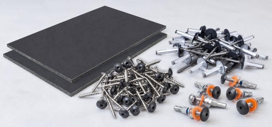
Fasten HPL sheets securely to timber, metal or aluminium. Learn which screws and rivets are suitable and how fixed points and sliding points are produced.
When fastening HPL sheets, it is not enough for the sheet simply to sit securely on the substructure. It must also be able to move as temperatures change without creating stress. The appropriate fixing depends primarily on the substructure: facade screws are suitable for timber, balcony screws for metal structures with an accessible rear side, and matching facade rivets for aluminium substructures.
In this blog, we explain how the different systems are used and what you need to consider regarding fixed points, sliding points and installation.
Fastening HPL – which fixing method is suitable?
Depending on the existing substructure, HPL sheets can be fastened with facade screws, balcony screws or facade rivets. These systems are not interchangeable at will because their threads, installation methods and suitable substrates differ significantly.
| Substructure | Suitable fixing | Installation principle |
|---|---|---|
| Timber | Facade screws with coarse thread | Screwed directly into the load-bearing timber substructure |
| Metal with accessible rear side | Balcony screws with metric M5 thread | Through-bolt installation with plastic washer, flat washer, spring washer and cap nut |
| Aluminium | Aluminium facade rivets | One-sided installation with a blind-rivet tool |
Important: For facades, balcony cladding and comparable structures, the installation instructions for the sheet and substructure and the requirements applicable to the project must be followed.
The matching sheets are available from us as HPL sheets cut to size.
Planning HPL fixings correctly before installation
Before drilling and fastening, the sheet format, sheet thickness, substructure and positions of the fixing points should be established. The number and position of fixings depend, among other factors, on the size and thickness of the HPL sheet, the substructure and the intended use.
HPL sheets with a thickness of 6 mm are suitable for smaller, evenly supported flat components. HPL sheets with a thickness of 8 mm are available for larger spans or higher loads. The appropriate sheet thickness therefore depends, among other factors, on the sheet format, support and subsequent load.
Consider thermal expansion
HPL sheets can expand and contract as temperatures change. They must therefore not be clamped rigidly at every fixing point.
Movement clearance must be provided between adjacent sheets and neighbouring components. The space required depends on the sheet format, possible temperature change and installation system used.
The possible dimensional change can be determined using a thermal expansion calculator for plastic sheets.
Rear-ventilated outdoor installation
For outdoor applications, HPL sheets should be fastened to a rear-ventilated substructure. This helps compensate for temperature differences and avoid long-term stresses in the material. The design of the substructure depends on the sheet format, installation situation and fixing used.
If HPL sheets are used as a free-standing privacy screen in the garden or on the patio, the panel size, posts, substructure, wind load, movement clearance and anchoring must be planned together as well as the fixings. We explain the complete construction step by step in the blog Build your own privacy screen from HPL sheets.
Information about preparatory machining can be found in our blogs on cutting HPL sheets and drilling HPL sheets.
Tip: The cutting, holes and fixing points should be planned together. This avoids unnecessary reworking and additional holes.
Fixed point and sliding points on HPL sheets
For stress-free installation, each HPL sheet is given one fixed point. The remaining fixings are designed as sliding points.
Purpose of the fixed point
The fixed point determines the position of the HPL sheet. The required hole diameter depends on the screw or rivet system used and the specifications of the relevant product.
Purpose of the sliding points
The holes for the sliding points are made larger. This leaves clearance around the screw or rivet shank so that the HPL sheet can move as temperatures change.
The fixing should be centred in the enlarged sliding point. If the screw or rivet already rests against the edge of the hole, the intended movement path is no longer available equally in every direction.
Important: An HPL sheet should not be fastened with several rigid fixed points. Otherwise, temperature-related movement of the sheet may be restricted.
Fastening HPL to a timber substructure
Stainless-steel facade screws are suitable for a load-bearing timber substructure. Their coarse thread is designed for direct fixing into timber.
The facade screws are available unpainted or with a UV- and weather-resistant head coating. For RAL versions, the colour and gloss level are matched to the corresponding HPL sheets.
Required tools and fixings
- HPL sheet: In the intended format and suitable thickness.
- Timber substructure: Load-bearing and suitable for the intended arrangement of the fixing points.
- Facade screws: Suitable stainless-steel screws with coarse thread.
- HPL drill bit: Suitable diameter for the fixed point and sliding points.
- T20 drive: For controlled insertion of the facade screws.
- For marking: Tape measure and a marking tool suitable for the surface.
Producing the fixed point and sliding points
For the installation described here, 6.0 mm at the fixed point and 8.0 mm at the sliding points serve as guide values. The specific hole diameters must match the facade-screw and installation system used.
| Fixing point | Guide value for the HPL sheet | Function |
|---|---|---|
| Fixed point | 6.0 mm | Positions the sheet |
| Sliding point | 8.0 mm | Allows temperature-related movement |
Tightening facade screws correctly
The screws are driven into the timber substructure with a T20 bit. The screw head should rest against the sheet surface but must not press the HPL sheet firmly against the substructure at the sliding points. The sheet must remain able to move.
Note: Facade screws for timber are not intended for direct fixing to a metal substructure. Balcony screws with metric threads are available for metal structures with an accessible rear side.
Fastening HPL to a metal substructure
Balcony screws with metric M5 threads are suitable for metal substructures and balcony railings, provided the rear side of the structure is accessible. The screw is passed through the HPL sheet and substructure and secured with a cap nut on the back.
Components of a balcony screw
- M5 screw: Stainless-steel screw with metric thread.
- Plastic washer: Self-adhesive plastic washer between the HPL sheet and substructure.
- Flat washer: Stainless-steel washer on the rear side of the structure.
- Spring washer: Stainless-steel spring washer for additional connection security.
- Cap nut: Stainless-steel cap nut for fastening on the rear side.
The thread-locking coating on the thread and the spring washer reduce the risk of the cap nut loosening by itself due to impacts or vibration.
Check the clamping range
The appropriate screw length is determined by the thickness of the HPL sheet and the material thickness of the substructure. Before ordering, check which clamping range is required for the particular construction.
Installing balcony screws
- 1. Mark the hole positions: Mark the intended fixing points on the HPL sheet.
- 2. Define the fixed point and sliding points: Plan one position-defining fixed point and the required sliding points.
- 3. Drill the HPL sheet: Produce the holes to suit the fixing system used.
- 4. Check the substructure: If the required installation holes are not already present, produce them to suit the screw system used.
- 5. Position the plastic washer: Place the self-adhesive plastic washer exactly over the hole so that it lies between the HPL sheet and substructure after installation.
- 6. Insert the balcony screw: Pass the screw through the HPL sheet and metal substructure.
- 7. Fit the retaining elements: Fit the flat washer first and then the spring washer on the rear side.
- 8. Tighten the cap nut: Screw on the cap nut and then tighten the connection to 2 to 4 Nm.
The required hole diameters depend on the balcony-screw system used and the design of the fixed and sliding points.
A T20 drive is used for the screw head. An 8 mm spanner is required for the cap nut.
Important: Balcony screws are suitable only for structures where the rear side is accessible for the flat washer, spring washer and cap nut.
If you are planning complete balcony cladding, the entire construction can be found in our DIY guide to balcony edging made from HPL sheets.
Riveting HPL to an aluminium substructure
Aluminium facade rivets are suitable for fastening HPL sheets to an aluminium substructure. As blind rivets, they can be set from the front. Access to the rear side of the structure is not required.
The facade rivets consist of an aluminium sleeve and a stainless-steel mandrel. They have a rivet shank with a diameter of 5.0 mm and a rivet head with a diameter of 16.0 mm.
Note: Aluminium facade rivets are intended for aluminium substructures. Facade screws are used for timber substructures.
Match the holes to the rivet system
The substructure and HPL sheet must be pre-drilled to suit the rivet system used. For the rivet system using the special HPL-16 nosepiece, 5.1 mm holes are provided in the aluminium substructure and at the fixed point.
For this system, the sliding points are made with larger holes from 8.0 to 10.0 mm. The size used within this range depends on the specific rivet and installation system.
Use the special HPL-16 nosepiece
The special HPL-16 nosepiece is used to prevent the sliding points from being riveted too tightly. It is designed for aluminium facade rivets with a 16 mm rivet head and 5 mm rivet shank.
When setting the sliding points, the nosepiece creates a defined gap of 0.3 mm between the rivet head and HPL sheet. This prevents the sheet from being clamped and allows it to move as temperatures change.
The special nosepiece has an M10 × 1 threaded connection and is compatible with riveting tools featuring a matching connection.
Important: The HPL-16 nosepiece is used when setting the sliding points. The fixed point, in contrast, is produced without this additional movement clearance.
Hole diameters for HPL fixings at a glance
The hole diameter required depends on the fixing system and whether the relevant hole is designed as a fixed or sliding point.
| Fixing system | Hole diameter in the HPL sheet | Note |
|---|---|---|
| Facade screws on timber | As guidance: fixed point 6.0 mm, sliding points 8.0 mm | Observe the requirements of the facade-screw and installation system used |
| Balcony screws on metal | To suit the fixing system used | Define the fixed- and sliding-point design according to the system used |
| Facade rivets on aluminium | Fixed point 5.1 mm, sliding points 8.0 to 10.0 mm | Observe the specifications of the particular rivet system |
Suitable diameters are available with our solid-carbide HPL drill bit. We explain the correct drilling technique, suitable backing and further machining guidance in our blog on drilling HPL sheets.
Defining edge and fixing distances
One universal fixing distance cannot be specified for HPL sheets. A small sheet on a closely supported substructure has different requirements from a large-format facade or balcony sheet. The fixing pattern must therefore suit the sheet, substructure and subsequent load.
The edge areas must also be supported adequately. Fixing holes must neither lie directly at the sheet edge nor be positioned so far inwards that unsupported sheet edges are not held adequately.
- Sheet thickness: A thicker HPL sheet may be required as the span or load increases.
- Sheet format: As the sheet size increases, an adjusted number and arrangement of fixing points may be required.
- Fixing: Screws and rivets differ in their shank, head and hole diameters and must suit the particular construction.
- Substructure: The position and width of profiles or battens determine where fixings can be placed appropriately.
- Load: Wind, dead weight and mechanical stresses affect the required fixing.
- Installation situation: Interior cladding has different requirements from an outdoor facade or balcony sheet.
Important: Binding edge and fixing distances must be established on the basis of the HPL sheet used, the fixing system, substructure and specific installation situation. The installation requirements applicable to the particular structure must be followed.
Common mistakes when fastening HPL sheets
- Incorrect fixing: Facade screws for timber, balcony screws for metal and facade rivets for aluminium must not be interchanged arbitrarily.
- Several rigid fixed points: Several fixings without movement clearance can restrict temperature-related expansion of the sheet.
- Sliding points made too small: An insufficient hole diameter restricts the intended freedom of movement.
- Fixing not centred: If the screw or rivet already rests against the edge of the sliding point, the movement path is not available evenly.
- Screws tightened too firmly: The sheet must not be pressed firmly against the substructure at the sliding points.
- Sliding points in the HPL-16 rivet system set without the special nosepiece: Without the correct nosepiece, the riveted connection at the sliding point may be made too tight.
Fastening HPL sheets: the key points at a glance
Whether using facade screws, balcony screws or facade rivets, the fixing must suit the substructure. HPL sheets are fastened to timber with suitable facade screws, balcony screws can be used on metal structures with an accessible rear side, and matching facade rivets are available for aluminium substructures.
Correctly producing the fixed and sliding points is equally important. While the fixed point positions the sheet, the remaining fixings must permit temperature-related movement of the HPL sheet.
Planning the sheet format, substructure, hole pattern and fixings together before cutting provides the best basis for clean installation that functions reliably in the long term.
Frequently asked questions about fastening HPL sheets
How are HPL sheets fastened?
Depending on the substructure, HPL sheets are fastened with facade screws, balcony screws or facade rivets. Each sheet receives one fixed point. The remaining fixings are designed as sliding points so that the sheet can move as temperatures change.
Which screws are suitable for HPL on timber?
Stainless-steel facade screws with coarse threads are suitable for a timber substructure. The facade screws are installed with a T20 drive and are available unpainted or with colour-coordinated screw heads.
Which screws are suitable for a metal substructure?
Balcony screws with a metric M5 thread, plastic washer, flat washer, spring washer and cap nut are suitable for metal substructures with an accessible rear side. The required clamping range must suit the thickness of the HPL sheet and substructure.
Can HPL sheets be riveted?
Yes. HPL sheets can be fastened to an aluminium substructure with aluminium facade rivets. For the HPL-16 system, a special nosepiece is used for the sliding points to produce a defined gap of 0.3 mm.
What is the difference between a fixed point and a sliding point?
The fixed point determines the position of the HPL sheet. The sliding points have larger holes and provide the sheet with the necessary movement clearance as temperatures change.
Which hole diameters are used for HPL fixings?
The hole diameters differ according to the fixing system and whether a fixed or sliding point is being produced. For facade screws on timber, 6.0 mm for the fixed point and 8.0 mm for the sliding points serve as guide values. The HPL-16 rivet system uses 5.1 mm for the fixed point and 8.0 to 10.0 mm for the sliding points. For balcony screws, the requirements of the system used and the particular structure apply.
How tightly may HPL screws be tightened?
The screw head should rest against the sheet but must not press the HPL sheet firmly against the substructure at the sliding points. A tightening torque of 2 to 4 Nm is specified for the balcony screws.